
Supporting Delayed-Branch Architectures in the MLTwist Disassembler
This is a web version of my bachelor’s thesis I defended last year. In case it would be useful to other people, I decided to publish it also here to make it more easily findable.
Prefer the original typeset version? View the thesis as PDF.
Introduction
Programmers usually write computer code in high-level programming languages, such as C. To run on a computer, this code needs to be transformed into much simpler instructions, which can be executed on the CPU. For compiled languages, such as C, this is done through the compilation process. A specialized program, a compiler, translates the high-level code into low-level instructions ahead of time.
In this process, much of the high-level information about the meaning and behavior of the program is lost,1 and much low-level, implementation-specific, CPU-specific information is added, crossing what is called a semantic gap.
Sometimes, it is very useful to try to recover the high-abstraction information about a program from its machine code. Whether it is to describe the program’s behavior to replicate it, to audit it, or other reasons. This discipline is called reverse engineering.
MLTwist is an experimental disassembler, a tool showing machine instructions in a readable format, that was created with the goal of allowing interactive instruction reordering with the guarantee that the reordering will not change the meaning of the program. This allows the user to undo compiler optimizations to make it easier to reverse engineer the program. MLTwist uses a platform-independent representation of instructions to achieve this, called intermediate code.
Delayed branching is a technique in CPU architectures designed to improve performance by mitigating internal CPU delays associated with program branches. In this approach, the execution of a branch instruction is postponed, allowing one or more instructions immediately following it to be executed unconditionally. These instructions occupy what is known as the delay branch slot. Although it has been largely superseded by more sophisticated branch prediction techniques, architectures that utilize it are still widely used today.
The primary aim of this thesis is to introduce support for architectures with delayed branches to MLTwist, as they were not representable before. Implementing this functionality is expected to require significant changes to MLTwist’s internal structure and representation.
SuperH 2E was chosen as the reference architecture for this implementation. The implementation of which also brings the requirement to support instructions operating on floating-point numbers.
Goals of the Thesis
Implement a generic mechanism within MLTwist to support architectures that utilize delayed branch slots. This design should ideally allow for straightforward integration of any such architecture in the future.
Add support for floating-point instruction representation in MLTwist’s intermediate code.
Introduce support for the SuperH 2E architecture to MLTwist, leveraging the newly implemented delayed branch slot and floating-point capabilities to achieve a level of functionality comparable to that of the existing RISC-V implementation.
Background
In this chapter, we will briefly go over the concepts important to achieving the thesis’s goal in both the MLTwist and SuperH architecture worlds. This will give us the necessary information and insight needed for a thorough analysis in the following chapter.
MLTwist Disassembler
MLTwist is an interactive disassembler that was developed by Jan Dubský as part of his Master thesis “Extensible disassembler with support for interactive instruction reordering”, defended at Charles University, in 2022 [Dubský (2022)]. It is written in the Go programming language.
The primary goal was to write an architecture-independent disassembler engine capable of reordering instructions in the disassembly of the program without changing the semantic meaning of the program. As Instruction scheduling — reordering of the program instructions to optimize the execution for the CPU pipeline — is a common optimization performed by compilers [Cooper and Torczon (2008)], this allows the user of the MLTwist disassembler to undo this optimization and recover more readable disassembly, while ensuring that they did not change the behavior of the program by accident. The disassembler engine should also be generic enough to support an arbitrary platform. This required designing a platform-independent instruction representation to which any instruction can be transformed and on which all the required analysis can be performed. This representation needed to understand the data (and other) dependencies between the instructions.
Among the goals of the thesis was also the possibility of execution emulation on an instruction-by-instruction basis, allowing the user to partially evaluate the program. This poses more requirements at the instruction representation. It needs to be detailed enough to fully capture the behavior of each instruction. It needs to capture how the instruction performs the operation, like, for example, addition, specifically, instead of just knowing that it depends on the operands. MLTwist understandably needed to make some compromises in this regard, as the problem of perfectly describing the behavior of i.e. system call instructions is very convoluted.
Dubský demonstrated the features of the disassembler by implementing RISC-V machine code support in his thesis.[Dubský (2022)]
Machine Code Parsing
First step in the disassembly process in MLTwist is to parse the raw instruction opcodes from the binary’s bytes to the internal platform-independent instruction representation. As machine code parsing is inherently architecture-specific, MLTwist offloads this task to the architecture implementation — a plugin implementing the instruction parsing. The architecture implementation exposes the interface in the form of Parse(addr model.Addr, b []byte) (model.Instruction, error) This function takes raw bytes of machine code and the address where they are located — this can be important for Program Counter (PC)-relative instructions — and produces an MLTwist instruction representation object or an error.[Dubský (2022)] This is what is called a parser in MLTwist [Dubský (2022)]
The obvious follow-up question is how MLTwist uses this parsing primitive provided by the architecture implementation to get the representation of the whole program. MLTwist supports Executable and Linkable Format (ELF) files as input. When opening a file, MLTwist takes all executable sections of the ELF and tries to parse the entire contents of them sequentially, transforming them into arrays of the internal instruction representations for later processing. This is what is called a sequencer[Dubský (2022)] in MLTwist and follows the disassembly method traditionally known as the linear sweep [Schwarz et al. (2002)]. The author himself admits that this approach to the process was not the best decision. As even the author’s reference RISC-V implementation cannot parse binaries produced by the Go compiler this way, because of non-code constants in executable sections [Dubský (2022)].
Instruction & Code Representation
To be truly generic, MLTwist requires an abstraction of what “instruction” and “code” mean across many different architectures. MLTwist solves this by defining Intermediate Code (IC) — a way of describing computing operations in an abstract, platform-independent manner. Similar to Intermediate Representation (IR) abstraction in compilers [Cooper and Torczon (2008)]. MLTwist is conceptualizing CPU registers as a key-value store and memory as an address-value store,2 where address is an unsigned integer. These stores hold expressions. An expression is either a constant or a function of expressions representing an operation. Expressions by definition result in a value — another expression. And are best visualized as trees — building more complex expressions from the basic ones. Each expression has a width, a length in bytes, that it operates on. Expressions are immutable. MLTwist supports the following types of expressions:
Const— a sequence of constant bytes of a given length.Binary— one of arithmetical addition, multiplication, division, bitwise left/right shift, and NAND, is performed on the two operands.Less— a conditional expression. It takes 4 operands, if the first operand is less than the second operand, it evaluates to a giventrueExpr, if not it evaluates tofalseExpr.RegLoad— loads an expression from a register specified bykey.MemLoad— loads an expression from memory specified by anaddressand an address spacekey.
Dubský tried to keep the list of expression types in the IC as short as possible, in the spirit of functional completeness [Enderton (2001)], for the sake of simplicity of implementation. So, for example, the IC does not include a subtract binary expression because it can be built from other expressions (using two’s complement and addition). However, MLTwist does provide an expression gadget library with such more complex expressions prebuilt [Dubský (2022)].
Nevertheless, the procedural nature of most platforms is not fully representable by just expressions. Machine code instructions inherently produce side effects that the next instructions depend on. To mimic this behavior, MLTwist introduces effects. Effect is by definition an arbitrary operation that results in a state change. Presently implemented effects in MLTwist are just assigning an expression to a storage. They are:
RegStore— stores an expression to a register specified bykey.MemStore— stores an expression to memory specified by anaddressand an address spacekey.
An instruction is therefore represented as an ordered set of effects. The Program Counter is just a regular register with a special reserved key that stores the address of the next instruction to be executed. Control flow branching is therefore just a write to this register [Dubský (2022)].
However, as recognized above, even this is not enough to represent all instructions. System call, CPU state change, and even wilder instructions do not fit this computational model. MLTwist tackles this by adding a type property to the instruction representation. It contains flags describing different special cases that can be set in naughty instructions. Instructions of special types receive special handling — i.e., setting the instruction to be dependent on all neighboring instructions during dependency analysis, notifying the user that a full emulation cannot be performed, etc.[Dubský (2022)].
There are also other properties that need to be present in the instruction representation. For the parser to determine where the following instruction opcode is located,3 a length in bytes of the just-parsed instruction is needed. And to know how to display the instruction to the user — also a very architecture-dependent task — a conversion to a string representation is needed. This is provided by the given architecture implementation and is also present in the produced instruction representation object [Dubský (2022)].
The struct representing an instruction in MLTwist, as part of the architecture implementation interface, looks like this:
type Instruction struct {
    Type    Type // uint64 containing bit flags
    Effects []expr.Effect
    ByteLen Addr
    Details PlatformDetails // interface implementing .String()
}
Dependency Analysis
Having a sequence of parsed instruction representations, MLTwist now needs to perform the analysis that will determine the possibilities of instruction reordering.
MLTwist does this by first dividing the code into basic blocks. A basic block is a sequence of instructions without any control flow changes; such a block is always executed as a whole [Cooper and Torczon (2008)]. Jump targets — locations that are destinations of jump instructions — cause the beginning of a new basic block, jump instructions cause the end of a basic block. The basic block are the “owners” of instructions in MLTwist. The program at this stage is represented as a collection of basic blocks.
Dubský recognized that moving an instruction outside of its original basic block does not make sense, as it by definition changes the control flow conditions under which the instruction will get executed — violating the control dependency [Dubský (2022)].
As a consequence, MLTwist only needs to perform the other dependency analyses in the context of one basic block, not the context of the whole program. This is much less computationally expensive. For every instruction in a basic block, MLTwist computes the set of forward and backward dependencies. Considering two instructions A and B executed in this order, the dependencies can be of the following kinds:
True dependency — instruction
Breads what instructionAwrites, thus instructionBneeds to be executed afterAAnti-dependency — instruction
Areads what instructionBoverwrites, thus instructionBneeds to be executed afterAOutput dependency — instruction
Awrites what instructionBoverwrites, thus instructionBneeds to be executed afterASpecial dependency — instruction
Bis of a special type (i.e. syscall) — we don’t know the real dependencies, thus instructionBneeds to be executed afterAjust in caseBdepends onA
Having precomputed forward and backward dependency sets for all instructions, storing them for each instruction, moving an instruction from one place to another is just a matter of checking that no dependency is violated and progressively swapping instructions. Returning to the example of the instructions A and B, if we want to swap them, MLTwist checks that B ∉ A.forwardDependencies and A ∉ B.backwardDependencies. Boundaries of an instruction are the closest dependent upper and lower instructions — delimiting the area where the instruction can be freely moved [Dubský (2022)].
The SuperH Architecture
SuperH (SH for short) is a 32-bit RISC-type Instruction Set Architecture (ISA) family first introduced by Hitachi in 1992, currently produced by Renesas. It was and is still widely used in embedded applications, including Sega game consoles, Japanese-made cars such as Subaru and Mitsubishi, and many others [SEGA Retro (2024); Wikipedia contributors (2025)].
Despite operating on 32-bit words, the instruction length is 16 bits.4 This property results in higher code density, increased cache efficiency, and lower memory requirements — great for low-end, affordable, embedded devices and not something common in the industry [Wikipedia contributors (2025)].
The ISA family follows the load-store model — arithmetic operations executed on registers, data is loaded from memory to them and then stored back.5 It offers 16 32-bit general purpose registers and 7 control & system registers [Hitachi America Ltd. (1996)]. Most of the branch instructions have a delayed branch slot — one more instruction is executed after the branch instruction before the jump is taken — the advantage of which is minimizing CPU pipeline stall.
Starting with the SH-1 architecture, over the years, many different additions to the architecture family have been made, progressively adding instructions and features. Examples include the Digital Signal Processing (DSP) — introduced in the DSP branch of the family, 32-bit and 64-bit IEEE754 floating-point instructions — introduced in SH-2E and SH-4 respectively, register banks — introduced in SH-2A, explicit cache operations — introduced in SH-4, etc. [Endo (2020); Wikipedia contributors (2025)]. The inheritance of instructions between different generations of SH can be seen in Fig. 1.1 taken from the source code of the GNU Opcodes Library [Free Software Foundation (1993b)].
                SH1
                 |
                SH2
   .------------'|`--------------------------------.
  /              |                                  \
SH-DSP          SH3-nommu/SH2A-nofpu               SH2E
 |               |          |`--------------------. |
 |               |          |                      \|
 |              SH3-nommu  SH4-nm-nf/SH2A-nofpu    SH3E/SH2A
 |               |\         |          |      \     |    |
 |               | `------. |     SH2A-nofpu   `----+---.|
 |               |         \|            \          |   SH4/SH2A
 |              SH3     SH4-nommu-nofpu   `---------+--. |   |
 |              /|\         |                       |   \|   |
 | .-----------' | `--------+---------------------. |  SH2A  |
 |/              |          /                      \|        |
 |               | .-------'                        |        |
 |               |/                                 |        |
SH3-dsp         SH4-nofpu                          SH3E      |
 |               |`-------------------------------. | .-----'
 |               |                                 \|/
 |              SH4A-nofpu                         SH4
 | .------------' `-------------------------------. |
 |/                                                \|
SH4AL-dsp                                          SH4A
Instruction inheritance graph for the SuperH family. Taken from (Free Software Foundation 1993b).
SuperH 2E
We focus on SuperH 2E in this thesis because it has the essential SuperH caveats, such as delay slots, floating-point instructions, and instruction-data mixing. Additionally, the fact that it lacks advanced features of its descendant architectures, such as double-precision floats, register banks, and vector instructions, makes it fit the scope of a bachelor’s thesis the best. This strategic position in the architecture family tree will enable us to implement the basis of SuperH support, allowing future extension to other SuperH architectures. So, although the vast majority of properties discussed in this chapter are applicable to SH-2E’s relatives as well, we will discuss primarily SH-2E from now on.
SH-2E’s good compromise between complexity and capability earned it a considerable market share in the automotive industry. It is commonly found in engine control units [Wikipedia contributors (2025)].
SH-2E was the first SuperH to support floating-point calculations. They operate on 32 bits and implement a subset of operations specified by the IEEE754 standard. Therefore, apart from the standard SuperH general purpose registers, SH-2E features 16 32-bit floating-point registers and 2 floating-point system registers.
Instructions
Format
The instruction opcodes in SH-2E have a fixed length of 16 bits. They have between 0 and 2 register operands — 4 bits used for each in the opcode for the ID of the register — and one of 0, 4, 8, and 12 bits in the opcode used for an immediate value. In some instructions the immediate value is zero-extended, in others it is sign-extended. The opcodes are specified with the most significant bit on the left in the ISA [Renesas Technology Corp. (2006)]. For example, the opcode of the ADD instruction is the following 0011nnnnmmmm1100 — nnnn represents the bits of the ID of the destination register, while mmmm of the ID of the source register [Renesas Technology Corp. (2006)].
Addressing Modes
Several different addressing modes are utilized by the instructions. Apart from the obvious direct — value of the register itself is used — and indirect — value in memory at the address held in the register is used — there are post-increment and pre-decrement indirect modes, indexed and displacing indirect modes, and PC-relative with or without displacement indirect mode [Renesas Technology Corp. (2006)].
The PC-relative mode is used to load 16- and 32-bit immediate values to the registers — such as absolute addresses, big indices, and so on. These values are stored right next to the code in the .text sections [Renesas Technology Corp. (2006)]. This will cause problems with code parsing, which are later discussed in section 2.1.
Delayed Branch Slots
The CPU instruction pipeline is a concept that divides the execution of an instruction into multiple stages. These stages can be processed in parallel on the CPU for multiple instructions. Once a stage has done its part of one instruction, it goes to process the next one, while the just-processed instruction goes on to another stage, similar to pipeline production in a factory.
The pipeline stages in a SH-2E CPU are [Renesas Technology Corp. (2006)]:
IF (Instruction fetch) — The instruction opcode is obtained from the address pointed to by PC.
ID (Instruction decode) — The instruction opcode is decoded to the appropriate signals.
EX (Instruction execute) — Arithmetic operation like calculation directly on registers or address calculations.
MA (Memory access) — Memory operations (read/write) are performed. This stage is present only with instructions that access the memory.
WB (Write back) — The results of memory read are written to a register. Present only on instructions that involve memory loads.
Usually, execution of one stage takes one CPU cycle. But because Instruction fetch and Memory access stages can take longer,6 we instead use the term “slot” to refer to the period during which a given stage of an instruction is processed. Because the CPU pipeline needs to stay synchronized, the other stages, even if they’re already done processing, are waiting for the last one to complete, before advancing the pipeline.
The execution of 3 consecutive instructions with all 5 stages by the CPU pipeline is depicted in Fig. 1.2. The slot number increases with time.
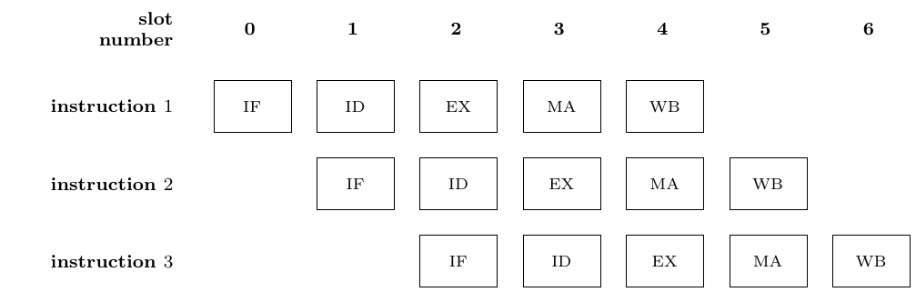
Illustration portraying linear pipeline execution. Inspired by (Renesas Technology Corp. 2006).
When loading instructions into the pipeline, only a linear code path is considered.7 This means that every time a branch is taken, there is a delay before the branch destination instructions are deep enough in the pipeline to start executing. This delay is what is called a pipeline stall. The address of the next instruction is unknown until after the Instruction execute stage of the branch instruction. So, before the correct destination instruction enters the Instruction fetch stage, it takes at least two slots of instructions that should not be executed — their results should be discarded. This can cause a significant slowdown and waste of computing power.
Because of the effort to achieve the best possible performance with limited hardware, minimization of CPU pipeline stall was one of the issues the designers of SuperH were addressing. They decided to take inspiration from the MIPS architecture introduced a few years earlier [MIPS Technologies, Inc. (1995)]. The approach is called delayed branching.
Principally, the CPU fully executes one more instruction from the linear instruction stream after the branch instruction — this additional instruction is in what is called the Delayed Branch Slot (DBS) or just delay slot. This instruction is already fetched by the time the CPU discovers that it is taking a branch. Thus, if the instruction in the DBS does not result in any additional memory access, the overhead is minimal. That is, even if the compiler (or programmer) does not want to fill this slot with something useful, a NOP instruction can always be placed there without any substantial performance drawbacks. However, if a useful instruction is placed there, it reduces the number of wasted slots from two to one. An example execution of an unconditional branch with delayed branch slot taken on a SH-2E CPU is depicted in Fig. 1.3.
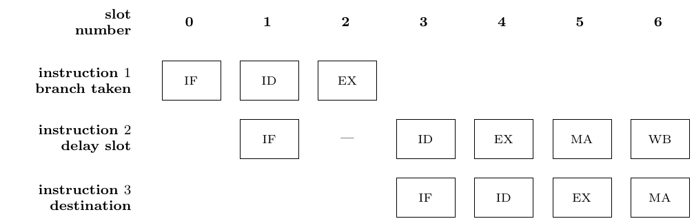
Illustration portraying pipeline execution with delayed branch slot. An unconditional branch is taken in instruction 1 and the following instruction is in a delay slot. The instruction 3 is at the branch destination address. Taken from (Renesas Technology Corp. 2006).
There are some instructions in SH-2E that use PC-relative addressing, so the natural question is how these will work when placed in DBS. Or even more obviously, how would another delayed branch instruction work when placed there.
The SH-2E ISA clearly defines the behavior in those cases. A branch instruction put in Delayed Branch Slot triggers the Illegal Slot Instruction (ILLSLOT) exception [Renesas Technology Corp. (2006)], stopping the execution of the program and causing an interrupt on the CPU. Interestingly enough, PC-relative data move instructions in DBS, like mov.w @(disp, PC),Rn, do not cause an exception, but instead the PC in those instructions is defined as the address of the branch destination + 2 [Renesas Technology Corp. (2006)]. But this behavior seems to have been deemed a mistake, as in the newer SH-4 architecture, this scenario would also cause the Illegal Slot Instruction exception [STMicroelectronics and Hitachi (2002)]. We will need to deal with this later when designing the delay slot representation.
In general, in CPU architectures, the approach of delayed branching has been obsolete since the beginning of this century. Modern CPU pipelines are much more complex than the simple five-stage design. They are super-scalar — they execute more instructions in parallel. More complex internally but externally simpler approaches, such as branch prediction, out-of-order execution, and others, are used to boost CPU performance [Alain Merigot (2019)].
Features beyond 2E
Floating-Point Instructions
SuperH 2E supports basic single-precision IEEE754 operations, specifically addition, subtraction, multiplication, division, fused multiply-add, comparison, floating-to-integer and back conversions. More features were added in later editions. The square root instruction was added in SuperH 3E.
Double-precision float support and vector instruction for floats were starting to be added in SH-2A, and fully supported in SH-4 and SH-4A [Endo (2020)]. Instructions like ftrv XMTRX,FVn that allow multiplication of a 4-by-4 matrix with a vector in a single instruction. The floating-point vector instructions are affected by the setting of the floating-point control registers, switching between the two floating-register banks, and setting other properties [STMicroelectronics and Hitachi (2002)].
Register Banks
Operating systems often have to handle interrupts from hardware, by the task scheduler, and for many other reasons. This requires switching the task contexts — most importantly the content of registers. As this context switching is happening very often, its optimization has a big impact.
SuperH 3 introduced register banks to the SuperH family. General purpose registers R0 to R7 are duplicated in two register banks — BANK0 and BANK1. The OS can switch between these two banks by setting the RB flag in the SR system register. By default, only BANK0 is accessible by userspace, which means that BANK1 can be used exclusively by the OS as a temporary scratch space. This speeds up context switching, as the kernel has these scratch registers available by executing only one instruction, for example, Linux does this [The kernel development community (2025)].
Support in Existing Disassemblers
SuperH is supported by the mainstream IDA Pro and Ghidra disassemblers, and the latter even has decompilation support [Hex-Rays (2025); Prototopia Forums, VGKintsugi (2019)]. The Rizin disassembler also supports SuperH in its intermediate language RzIL, although it lacks support for delayed slots and some other features [DMaroo’s personal blog (2021)].
As Ghidra and Rizin are open source, we can use their implementations as a reference in later chapters [National Security Agency (2025); Rizin Organization (2025b)].
Analysis
With the relevant concepts laid out, let us dive into how to put them together in the process of achieving the goals of this thesis.
Machine Code Parsing
Parsing SuperH instructions is fairly straightforward. SuperH instruction opcodes can without a problem be matched using MLTwist’s provided opcode matcher. We specify the hard-coded bits and a mask for the variable bits — a register number, or an immediate value — for each opcode. The matcher can then be used to implement the parser interface. This confirms that this component is nicely platform-independently designed.
Problems start to arise in the sequencer part of the machine code parsing process. SuperH offers PC-based memory indexing for some data move instructions, i.e. mov.w @(disp,PC), Rn — moving a 16-bit word from a PC-relative address to the register Rn [STMicroelectronics and Hitachi (2002)]. These instructions allow read-only constants to be stored right next to the executable code in the .text section. Compilers especially like to store jump tables in this way [Cifuentes and Van Emmerik (1999)]. This greatly improves code density — no need to store large displacement offsets — and cache locality — a greater chance that the constant will already be in cache thanks to prefetching — parameters important for embedded architectures. But from the perspective of a disassembler using linear sweep to parse the instructions, this is problematic. We have seemingly no easy, concrete way of determining what is an instruction and what is data.
The simplest approach is to say “If we can parse it as an instruction, then it is an instruction. If we cannot parse it as an instruction, it is a constant”, while preserving the linear sweep of the whole .text section. This is, for example, what the objdump utility does [Free Software Foundation (1993a)]. For its use case of a simple disassembler it is sufficient, for our use case this can cause problems. Parsing a non-instruction as an instruction can cause unexpected behavior during the analysis process. Specifically, the instruction could cause a jump to invalid code or the middle of some unsuspecting basic block, causing it to split. Given the instruction length of 16 bits in SuperH, this would happen quite often.
Or take a case where on architectures with variable instruction length, like the SuperH 2A [Renesas Technology Corp. (2005)], the constants land at the beginning of a valid code that is an indirect jump target that we fail to detect as such. The constants could cause the first instruction of the real code to be interpreted as a part of the last falsely-identified instruction, offsetting the opcode parsing for the rest of the program, generating completely invalid code. In case of malware, the code could be designed in such a way on purpose. All of these are well-described issues with the linear sweep disassembly method [Schwarz et al. (2002)].
Another approach is the recursive traversal method — parsing only the code that is reachable when executing the program [Schwarz et al. (2002)]. The ELF file contains an entry point address from which execution starts. We could follow the execution of the program, analyzing the code branches as we discover them, progressively reconstructing the Control Flow Graph (CFG). Dubský also proposes this method, but decides against using it, as they find it harder to implement and not 100% reliable anyway [Dubský (2022)].
Indeed, the problem of reconstructing full CFG is hard. The reachability problem, Rice’s theorem, by extension the halting problem, and their undecidability set a hard barrier as to how far such an automatic static analysis can go in full generality [Hopcroft et al. (2006)]. We will never achieve anywhere near 100% reliability and accuracy when reconstructing CFG in the general case; indirect jumps do not allow us.
State-of-the-art solutions combine many different techniques, such as pattern matching of known compiler-specific constructs, symbolic execution, interleaved symbolic execution, backward slicing, and value set analysis for CFG reconstruction from machine code [Cifuentes and Van Emmerik (1999); Shoshitaishvili et al. (2016); Gritti et al. (2020); Křoustek (2015); Cojocar et al. (2017)]. These techniques work fairly well on compiler-produced code, but implementing them for MLTwist could easily be a topic for a thesis of itself — way outside of our scope.
Fortunately, our goal is not to have the perfect automated CFG analysis. As we are writing an interactive disassembler, we can partially offload this task to the user. We can automatically do a best-effort analysis and code discovery using the recursive traversal method on the entry point, and provide the user with an option to later tell us about an arbitrary address “This is code”. We can then run recursive traversal again on the user-provided address, hoping to discover more branches to analyze. Slowly, with user assistance, we build the full CFG of the program.
The automatic recursive traversal can, for now, only discover direct jumps, and we design it so that it is possible to improve it later, i.e. by implementing one of the many techniques mentioned above, making it discover more code and making the user do less manual work as it improves.
Switching from linear sweep to recursive traversal solves the problems with data and instruction mixing but requires a major redesign of the internals of the disassembler engine. In particular, the above suggested on-demand code parsing is not compatible with the current parser-sequencer parsing and code representation model. However, as becomes evident in the later sections, we will need this redesign anyway to give MLTwist a more flexible and extensible representation of code.
Instruction Representation
As established in the first chapter, MLTwist uses IC to represent the meaning of instructions. Most of the SuperH instructions — like data transfer, arithmetic and logic instructions — are easily representable using the existing IC expressions and effects. However, there are few notable exceptions.
Delayed Branch Slots
In the current representation, there is really no way to represent delayed branch instructions. Dubský acknowledges this limitation and states that this would add complexity to the otherwise fairly simple implementation, all because of a feature that no other mainstream architecture (other than MIPS) has [Dubský (2022)]. However, if we want to accomplish the goals of this thesis, there is really no other way around it. In this section, we discuss the obvious and less obvious potential solutions to this problem.
The first instinct might be to completely eliminate the delay slot. Since we can already easily move instructions in MLTwist, the idea might be to just swap the delayed branch instruction with the instruction in Delayed Branch Slot. Although applying this transformation would be technically simple, this approach has a fatal flaw. There can be an anti-dependency between the two instructions. Consider a conditional branch instruction that jumps or does not jump based on the value of the T flag with an instruction to clear the T flag in DBS. This is allowed as the decision to jump or not jump happens before the clearing takes place.8 Thus, the swap would drastically influence the behavior of the program.
Another simple approach could be to note that the Delayed Branch Slot (DBS) is always at the end of a basic block. After evaluating the delayed effect, the control flow possibly changes, making it the end of a basic block. We could therefore design the delayed slot in MLTwist as a special property of the basic block representation — a special slot at the end. This is the approach that the Ghidra disassembler takes.
Ghidra supports Delayed Branch Slots in the representation of a basic block SimpleBlockModel. The DBS in the architecture needs to adhere to the following assumptions: ”
A delayed instruction always corresponds to a change in flow and terminates a block. The delay slot instructions following this instruction are always included with the block. Therefore, delay slot instructions will always fall at the bottom of a simple block.
The delay slot depth of the delayed instruction will always correspond to the number of delay slot instructions immediately following the instruction. The model may not behave properly if the disassembled code violates this assumption.
” [Ghidra Decompiler Java Documentation (2025)].
These assumptions are reasonable for such an approach and indeed SuperH, and many other architectures, do not break them. However, there are still a few problems that we would need to face if we would go with this in MLTwist.
First of all, since instruction reordering is one of the key features of MLTwist, how would moving instructions from or to the DBS work? One way would be to forbid touching instructions in the DBS at all — the same way branch instructions are handled. This seems overly restrictive, since most of the time the instruction in the DBS is not dependent on the branch instruction. So we could add a special handling of delayed branch instructions in dependency calculations to allow moving the instruction in DBS around if it does not break anti-dependencies. We would still need to figure out the problem of moving the branch instruction itself, i.e. by making all the instructions in the basic block, except the one in the DBS if there are no anti-dependencies, depend on it. However, having such complicated, possibly architecture-specific logic would pollute the otherwise clean IC and dependency analysis engine of MLTwist. In the previous section, we also realized that we will possibly need a more flexible model than the static basic-block-based one currently implemented. Combining this new flexible, on-demand code parsing with basic-block-based delayed effects would only complicate things further.
Moreover, programs that jump directly to an instruction within a DBS would trigger numerous edge cases in this model. A conflict arises because the instruction is expected to be in the DBS of the preceding code block, but it is actually located at the beginning of a completely new basic block. The system would need to handle this discrepancy in some way.
Another aspect is that there are architectures with much more exotic delayed branch slot behavior that MLTwist, as an experimental disassembler, might want to support one day. For example, PA-RISC, an architecture introduced by HP in the 20th century, supports having nested DBS — delayed branch instructions inside a DBS of another delayed branch instruction [HEWLETT-PACKARD COMPANY (1994)]. Or DSP architectures utilizing software pipelining — moving the pipelining burden to the compiler — like the Texas Instruments TMS320C6000, feature even non-branch instructions with delay slots, i.e., load, which has delay slot of length 4 on the TMS320C6000.
If we used the basic-block-based approach and someone would ever decide to support those architectures in MLTwist, they would not be able to reuse any of the code we have written to support SuperH, and they would need to start over. This is not ideal.
With all these pitfalls and arguments laid out, let us see if we can build something a bit more generic.
The Generic Delayed Effect
An important observation about program semantics is that whatever we do, in terms of MLTwist’s IC, the order of Expr evaluation and Effect application needs to stay the same to preserve the program meaning. This change in perspective from instruction to Exprs and Effects is very useful.
From this perspective, instructions with delayed effects, such as delayed branches or loads, are very similar to any other instruction. The key distinction is that one or more of their Effects are delayed: they are not applied immediately upon the instruction’s completion but after a set number of subsequent instruction cycles, or “slots”. It is crucial to note that while the application of the effect is postponed, its underlying expression – such as determining whether a branch will be taken – is usually evaluated immediately. See Fig. 2.1.

Showcase of a delayed branch instruction jump.s with a delayed slot of length 1 through the effects point of view.
If we return to the instruction paradigm, there is also a useful way to view this. A hypothetical instruction jump.s A, that has a DBS of length 1, can be divided into two instructions mov A, tmp — this evaluates the expression A, which can be a register or memory access, and moves it to some unique temporary pseudo-register tmp. After, or rather at the same time as the unrelated instruction in DBS, there is jump tmp — this takes the pre-evaluated value from tmp and just executes the write to PC. See Fig. 2.2. These delayed effects are something we can model in MLTwist’s IC.

Division of an instruction with a delayed effect into two instructions.
We will be extracting the delayed effects out of the delayed-effect instruction into a new pseudo-instruction that will be placed in the code where the effects are actually applied. The original instruction and the extracted delayed effects will have a true dependency between them.
Note that this approach is very flexible. If we were very lazy during the implementation, with this approach we could just add the upper and bottom half parts of the delayed branch instructions and reuse all the existing dependency analysis. If we then wanted to move the instruction from DBS, we could try to do that, relying on the dependencies to stop us if it were not possible. If we wanted to have an instruction with delayed slot of length 4 in which it was possible to nest other delayed slot instructions, it would be representable using this approach.
We have introduced a means of looking at delayed effects during dependency analysis. But we have yet to think about how we will specify delayed effects in the architectures or instruction themselves. And how to then transform the specification to dependency analysis means.
For the specification of delayed effects in instructions, we can add a new special type of Effect for them, called DelayedEffect. This delayed effect would be just a wrapper around some other effect — the real memory/register write — with additional information about the delay after which it should be applied. It could be as simple as this:
type DelayedEffect struct {
    // Number of slots the effect is delayed by. (uint)
    delay Delay
    // The effect to be applied.
    effect Effect
}
This will allow us to have multiple delayed effects in one instruction — necessary i.e. for SuperH’s bsrf instruction that has a delayed write to both PC and PR (the return address) registers. Also, it makes it possible to mix delayed and non-delayed effects, or even have delayed effects with different delays in one instruction.
Delayed Effect Processing
We already decided to use recursive traversal to parse and analyze the code, so we might as well reuse this traversal to process delayed effects as well.
Upon encountering an instruction that has delayed effects during the traversal, we can add them to a priority queue of effects pending to be applied, sorted by the number of instructions before their application — the delay — that we will decrement over time. When an effect in the queue reaches delay zero, we apply it at the location we are currently processing.
For nested delayed effects, or just for branches when we still have some delayed effects pending, we can make a copy of the current pending delayed effect queue and use this copied queue at the branch destination, like a checkpoint of the CPU state to which we can return. See Fig. 2.3. We could even save those checkpoints made during analysis, so we can later return to them when analyzing the code again, i.e., when we would discover a new jump destination of a jump in a DBS.
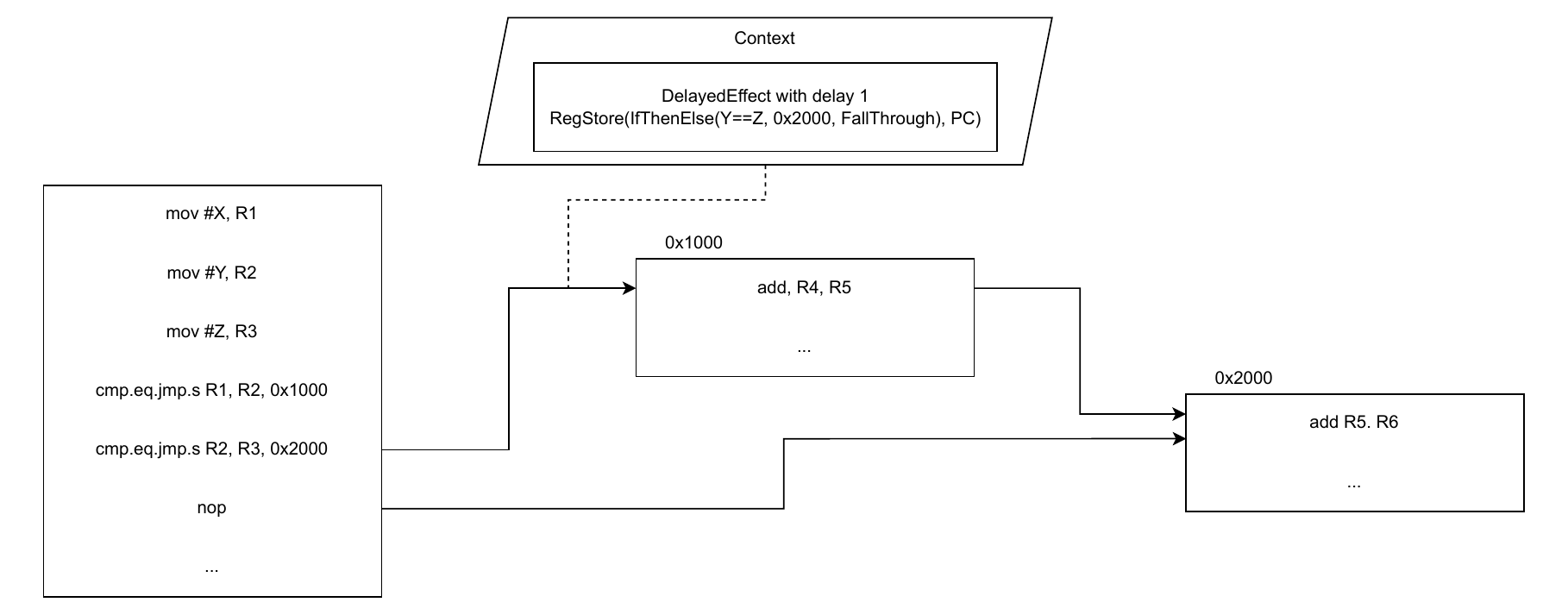
Showcase of handling nested Delayed Branch Slots during analysis on architectures allowing them. cmp.eq.jmp.s is a fictional instruction branching to specified address if its first two arguments equal with a DBS of length 1.
Of course, one could think of many situations in which this process will break. But we argue that almost all of those situations will not make sense on a reasonable CPU either. Or at least, it will not come from a reasonable compiler for that CPU. Let us consider the pseudo-assembly we would like to analyze in Fig. 2.4.
jmp_delayed2 A
jmp_delayed1 B
jmp_nondelayed C
Example of pseudo-assembly breaking delayed effect processing.
When the analysis reaches the jmp_nondelayed instruction, it will have 3 conflicting effects wanting to write to PC. But when a CPU executes this code, it will end up in exactly the same situation. This is the benefit of having an analysis that models CPU execution. What it will then do is up to the behavior specified in ISA. It might throw an exception, it might take the last effect, it might resort to undefined behavior. For now, we can just pick one behavior, say, make such situations throw an error, and go with that. Plenty of other scenarios (even more involved) can be found once we add loops, memory writes, etc.
We think it is safe to assume that these scenarios will happen mainly in the contexts like handcrafted obfuscation on the relevant architectures, so it is kind of expected that the analysis will not work in such cases. We also think that it should be the responsibility of future authors of the architecture implementations to add proper handling of the specific cases — even though we strive to make it as easy as possible for them, we cannot think of every possible case on every delay slot architecture in existence.
In the case of SuperH 2E, we are lucky not to have to deal with nested DBS. The delay effect behavior is straightforward, with the exception of mov.w @(disp, PC), Rn when placed in DBS. Its behavior of taking the jump destination address +2 as the value of PC when evaluated in the DBS turns out to be a major headache in this model of delayed effects. If such an instruction were to be present in the DBS of a conditional jump, the value written to the destination register would depend on whether or not the previous jump was taken. We could try to model this in the IC as a symbolic expression representing the jump destination address of the pending jump. This symbolic expression would then be resolved during emulation to the correct address. However, it would also require either passing on information as to whether the instruction is currently in the DBS, or setting this expression to a very platform-specific value of PC+2 when this instruction would not be in the DBS,9 so the same calculation could be used to obtain the desired load address. Both approaches would require adding a lot of complexity to the instruction implementation and instruction analysis and emulation.
There were, however, three more reasons that tipped the balance on why we decided not to support this behavior at all in MLTwist. The first was a string representation of such an instruction in the disassembly. Therefore, a simple display of the source address, which is customary in SuperH disassembly, would be infeasible. It would either require the full context of the instruction state within a DBS or necessitate other changes to the IC. Second, compilers are highly unlikely to produce such code that will have PC-relative loads in the DBS, or frankly, even know about such specific behavior. As we are targeting compiler-generated code, we could accept not supporting this instruction in a delayed slot as a fair limitation. Even more so, and this is also the third reason, this behavior concerns only SuperH 3 and below. In SuperH 4, this instruction in a DBS will result in an Illegal Slot Instruction (ILLSLOT) exception.
Therefore, the obvious way out of the problem is to model this SuperH 4 behavior even on our SuperH 2E implementation, and that is also exactly what we decided to do. We will make mov.w @(disp, PC), Rn and other PC-relative instructions throw Illegal Slot Instruction when present in a Delayed Branch Slot.
When initially thinking about delayed effect processing, we thought it might be beneficial to take inspiration in compilers’ division of analysis into passes, and divide CFG recovery recursive traversal and delayed effect processing into two independent passes. However, this turns out to be impractical. The two processes are very closely tied together. To reconstruct CFG we already need the processed delayed effects, as they are often the ones that change the control flow via delayed branch instructions. But to add the delayed effects we need the CFG, otherwise it is unclear where the pseudo-instructions applying the delayed effect results should be placed.
An attentive reader might notice that even this approach, in the end chosen to implement the delayed branch slots, also did not fully solve the instruction in DBS as jump target problem. It is possible to have an instruction jump target on an instruction in DBS and then the dependencies prevent it from being moved. The problematic scenario is when we discover this jump target after we already moved the instruction. This situation is equivalent to a dynamically discovered jump target in the middle of a basic block, which was already a problem recognized by Dubský [Dubský (2022)], so we really did not add any fundamentally new problem. This problem could be partially solved by tracking moves of instructions and alerting the user (and potentially reverting the move) if a new jump target is detected that would violate the control dependencies of the instruction affected by the move.
Fall-through Jumps
Usually conditional-jump instructions either branch to an address, thus changing the control flow, or not branch, falling through to the next instruction and continuing the execution in the same stream of instructions as before.
In MLTwist’s RISC-V implementation, this was done as a conditional expression, evaluated either to the branch target address or the calculated address of the next instruction. Whether an instruction is a branch or not was also implemented in this way, checking if it can write to PC some other value than the address of the next instruction.
This is problematic when adding delayed effects. Because there is another instruction between the delay branch instruction and the fall-through instruction, we cannot calculate its address simply by adding the current instruction length to the current instruction address. One idea would be to add two times the instruction length to the current address, but that would not work on architectures with different instruction lengths — the instruction in the DBS can have a different length than the branch instruction. We therefore need a way to represent this fall-through address in delayed jump instructions.
One way to do it would be to provide the instruction that contains the jump context about the instructions around it, so it is possible to calculate the respective address n slots ahead inside the instruction representation. This would require even a bigger redesign of the parsing process, because at the moment the calculation of instruction relative addresses is done before the instruction leaves the parser. And at that point, the instructions following the current instruction are usually not even parsed. We would need to somehow split it into two stages.
A better approach might be to symbolically represent this address and evaluate it later. Since instructions or delayed effects cannot be moved because that would break the control dependency, we can count on that this symbolic expression will always evaluate to the same value, even when this evaluation happens as we are analyzing or emulating the code.
Floating-Point Operations
To support architectures with floating-point instructions is to find a way of representing them in MLTwist’s IC. Usually, those instructions also operate on special floating-point registers. Like the FR0-FR15 registers on SuperH 2E, or f0-f31 on RISC-V “F” extension.
Since registers in MLTwist are just expressions identified by a key, we just need to solve the problem of representing constant float values and float operations in the MLTwist expression ecosystem, and the rest will come with it.
To represent constant float values, we could use the already present Const expression type in MLTwist. As we know, Const stores an array of constant bytes of fixed length. This is normally used to represent integer values or other constant data. We could convert the floating-point value into this byte representation as described in the IEEE754 standard [“IEEE Standard for Floating-Point Arithmetic” (2008)], and then work with it as standard bytes. If we needed to evaluate a float operation on a byte-encoded floating-point number, we could either do the operation directly on the bytes using normal integer MLTwist expressions, or we could convert the bytes back to standard float (the float32/float64 type in Go), perform the operation on that variable, and then convert the result back to the byte representation. Another approach might also be to add a completely separate FloatConst type, which would be used to differentiate between integer and float constants.
Although this last approach might sound good at first, we must realize that in hardware, in memory or the registers, there is no differentiating floats or integers either. Bytes are just bytes, and the interpretation is left up to the point when they are interpreted by some operation. A pointer can be dereferenced, a number can be added, and a float number can be added, but in a completely different way. But this is not clear before the operation is actually done on the value. There might be i.e. compiler optimizations that will access otherwise float value as integer. Keeping constant expression just as a view on bytes of some width is much more flexible. It might make sense to keep track of which expression is accessed in which way, as it might be very useful to the user, but that is not a topic for this chapter.
Having decided to support constant floating-point values via the existing Const expression, now we need to think about how to implement the operations themselves.
When Dubský designed the original IC, they determined that it should be “as simple as possible, so we will try to avoid having instructions that could be represented by a sequence of other instructions in our intermediate code” [Dubský (2022)]. IEEE754 represents floating-point numbers as two integers — exponent and significand — and a bit flag — sign [“IEEE Standard for Floating-Point Arithmetic” (2008)]. We could implement floating-point operations using existing integer expressions in MLTwist. This would have kept the IC truly minimal and should be achievable. Without modifying the IC, just by adding some pre-built expressions to the expression library, we could add support for IEEE754 floating-point numbers. But the resulting expression would be massive since there are many conditions and special cases when it comes to handling floats. From NaNs, to infinities, differently formatted zeros; the expressions would have had to handle it all. For the basic float support, we also need not only addition, multiplication, and division, but also comparison, integer-to-float, and float-to-integer conversions. This would require adding a lot of really convoluted expressions to the expression library. Because of limitations of expressions, this would mean a lot of duplicated code in the expression tree, which might slow down expression evaluation and dependency analysis.
Here also comes a little dissension we have with one of the design decisions made in the original MLTwist. We think that keeping the IC language minimal does not make much sense in the context of reverse engineering tools. The overall goal of the tool and the first and foremost goal of the tool users is to recover the lost abstraction and semantic meaning of the program. However, keeping the IC minimal does the opposite. A xor instruction in the code is converted to a series of nand operations. The semantic information that this was once a xor is lost, not gained. We acknowledge that the semantics of the instruction in just the disassembly context can be different from the true semantics of i.e. the whole function, because of compiler optimizations or other reasons.10 Then dropping abstractions and rebuilding them again might be beneficial. But we argue that even then having information about the instruction operation makes sense, because a lot of the deoptimization methods, like pattern matching, might rely on the instruction-specific information. If we were to replace floating operations with massive integer expressions, the loss of abstraction would be gigantic.
So, it seems reasonable to add new expressions to MLTwist’s IC to represent floating-point operations. These expression operations can use the standard math operations available in Go when evaluated. For that they will first need to convert the argument’s bytes to Go’s float type. And then convert back the result to bytes inside constant expression.
Degree of Support
The IEEE754 standard covers pretty much all operations that one might have to do with floating-point numbers. As we already learned, SuperH 2E only supports addition, subtraction, multiplication, division, fused-multiply-add, and conversion from/to integers. This is a nice basic feature set for working with floating-point numbers.
We can implement the operations needed by SuperH 2E now as a proof of concept, and further operations can be added later when some future architecture needs them. The process of adding a new operation is not that complicated, as we decided to reuse Go’s math operations — the standard math library — to evaluate them, instead of trying to write them ourselves.
Code Representation
We realized both in Machine Code Parsing (section 2.1) and Delayed Branch Slots (section 2.2.1) that we will need a code representation redesign. It needs to meet all the previous requirements imposed by MLTwist. Namely, allowing instructions to be moved around while not breaking dependencies and also allowing the dependency calculation itself to be efficiently performed on the instructions. Now, we also need it to handle the dynamic addition of code and the representation of delayed effects.
The main problem we have with the current representation is that it is not flexible when adding new analysis information. A data structure composed of a list of basic blocks – which is fundamentally a list of lists of instructions – is well suited for static, one-time construction, but proves inefficient for incremental modification. If we found a basic block in the middle of other basic blocks, we would need to copy everything, the indices would shift, and possibly we would also need to join this new basic block into some other basic block. Overall, a lot of logic and unergonomic behavior for the user.
A better idea seems to be to use a search tree to store the code representation. We could use the natural means of indexing in a program, the addresses, as keys, and then insert individual instructions into this tree. In this way, we can easily insert newly analyzed instructions between some other instructions. The address of the instruction will not change, unless the user moves it. This brings us to the problem of representing basic blocks in this representation. We need basic blocks not only for user convenience but more importantly for bounding the instruction dependency calculation.
We could add special nodes into the tree that represent the basic block starts and ends. As we know, a start of a basic block is caused either by a jump target or the end of the previous basic block, and the end of a basic block is either a branch instruction or a jump target on the following instruction. We can realize that the end markers would already be present in the tree as the branch instructions. So what we are missing are the start markers, or more specifically the jump targets.
Here, we can make an important observation: being a jump target is not a property of the instruction that is the jump target, but rather the address at which this instruction is located. Yes, the instruction cannot be moved above the jump target; otherwise, the control dependency would break. But it is the branch instruction creating this hard barrier on the jump target address and then the surrounding instructions depending on this barrier, rather than a direct dependency. We can represent this barrier in the tree, marking which addresses are jump targets and using those as basic block starts.
With these markers in place, there is really no necessity of having basic blocks as the owners of instructions or even as some metadata in the code. We can rather look at the basic blocks as a “view” over the code, which shows the control flow boundaries. This view can be generated after the instructions have already been added to the tree, and more importantly, instructions can be added to the tree without caring about basic blocks. The basic blocks can then be used during the dependency analysis as was done previously, mainly to reduce the number of instructions for which data dependencies need to be calculated.
It will also be necessary to add the delayed effect representation, as we envisioned, to the tree. For this and for the jump target representation, we will need the ability to store multiple objects at one address in the tree. This could be done as a simple list.
Summary
In this chapter, we have analyzed the necessary modifications needed to support SuperH 2E in MLTwist.
We decided to use recursive traversal from entrypoint for code parsing, while in the same traversal we will keep track of delayed effects and add “applying” pseudo-instructions at the correct places. Because we recognized that many code paths will be undiscoverable by a single recursive traversal pass, we set to allow the user to run on-demand code parsing on specified address.
We decided to introduce DelayedEffect to represent delayed effects in the IC. In the instruction definition, we can use it to define an effect that should be applied after a delay counted in slots (instruction cycles). The wrapped effects will be placed at the correct place (n slots away from the instruction having them) as pseudo-instructions, during the analysis traversal. We realized that this approach allows many obscure architectures to be representable. While only bringing the fundamentally unavoidable problems. We concluded that it is necessary to add a new symbolic expression that will represent a jump not being taken, as with delayed effects the fall-through address is not known at instruction-parse time.
It was decided that the floating-point number representation would use the existing Const constructs. While float operations will be represented as newly introduced specific expressions. During their evaluation, we decided to use the standard Go math operation to calculate the result.
We argued for a new, more flexible, code representation. To provide this flexibility, the new representation stores instructions in a search tree, using their memory addresses as keys. Basic blocks, previously the owners of instructions, will now become just a view over this tree. The basic block boundaries will be made by special objects in the tree representing jump targets and branch instructions (or branching delayed effects). We will need to store more objects at one address in this tree, as we are working not only with instructions, but also with delayed effect and jump target objects.
Design & Implementation
In this chapter, we will focus on solidifying the concepts of the previous chapter and turning them into concrete software form. A scheme of the final architecture is shown in Fig. 3.1.
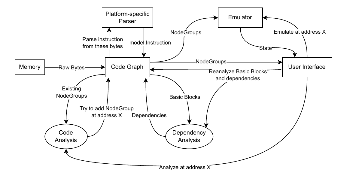
Overall diagram of MLTwist’s architecture (simplified)
We have divided the architecture into multiple components that we will go over now.
Code Graph
We need a central data structure that will house the search tree containing all the program’s instructions, as we proposed. Ideally, we picture this data structure as the single source of truth, a representation of all the state about the program needed by all the different MLTwist components to function. This is mainly the instruction tree, but it is also the entrypoint, program memory, and error messages.
During analysis, but also during other processing we might want to do with the code graph, errors or discrepancies can occur. We established that we don’t want MLTwist to exit on those errors but rather inform the user about them and leave up to them what to do next. Keeping the human in the loop in such cases. We can store these messages in the code graph as well as they are directly related to the code itself.
Having all important information about the program in one place will not only spare us possible synchronization issues, enable us to better reason about the different program logic, but it also allows us to more easily implement serialization and saving of that program state someday in the future.
For the search tree, we choose a B-tree, a widely-used generalization of a binary search tree, that allows one node in the tree to have multiple children, parametrized by the degree n, the maximum number of such children. This makes B-tree a more cache-friendly alternative to a binary tree. But we chose the B-tree mainly because there is a mature and generic implementation of it, by the Go creators themselves, Google, in the btree Go package [Go Packages (2024)].
While designing code graph, we tried to make it as encapsulated as possible, which means that we designed the public methods in a way that preserves internal consistency. For example, we decided that moving instructions will be done inside code graph, or creating a group node should be possible only by parsing an instruction. This will make any component that will want to add new instructions, like during analysis, not have to worry about the specific parser or memory that is needed, and offload this responsibility to the code graph.
Although this approach sounds reasonable, when combined with the fact that we are trying to make this component central dependency of many other components, as we later saw, this approach is not that elegant. A better approach could be to keep the code graph as a simple storage and move the remaining logic to a different package and add clearly defined interfaces between them. Or, as was originally done, keep the analysis and dependency analysis in the same package as code graph. However, that makes them less interchangeable.
Node Group
Since we can have an instruction, delayed effect, and jump target present at the same address, we need a way of grouping all those to store them in the B-tree.
We will call this group a NodeGroup and the generic node concept, which will represent either of the three types, a GraphNode.
The NodeGroup could be as easy as an address and a simple list of GraphNodes, our implementation is the following:
type NodeGroup struct {
    addr                    model.Addr
    instructionNode         *InstructionNode
    originalInstructionNode *InstructionNode
    enrichingNodes          []GraphNode
}
The InstructionNode, representing the instruction object, got its own property because it is a bit different from the other two types. First, there can be only one InstructionNode in a NodeGroup, while there can be virtually unlimited number of jump targets and, less likely, but still possibly, unlimited number of delayed effects being applied. Second, in the current implementation, there cannot be a NodeGroup without InstructionNode. As NodeGroup can only be created by parsing an instruction, there is no way to create one without an instruction associated with it. This is reasonable as jump target or delayed effect without an instruction at the same address also does not make sense.
Even if we allow moving instructions, it might also be useful to keep track of the original instruction that was present at that address. Although this is unused now, it might be useful in the future, i.e. for tracking dependency violations when splitting basic blocks.
Node Types
Although they are quite different, it is a good idea to have a shared interface for the GraphNodes. Their common trait, in addition to being a child of a NodeGroup, is mostly the ability to form dependencies on other GraphNodes. Thus, the interface will look the following:
type GraphNode interface {
    Parent() *NodeGroup
    SetParent(*NodeGroup)

    ForwardDependencies() GraphNodeDependencySet
    BackwardDependencies() GraphNodeDependencySet

    ExecuteBefore(GraphNode) error
    ExecuteBeforeOrAtOnce(GraphNode) error
    ExecuteAfter(GraphNode) error
    ExecuteAfterOrAtOnce(GraphNode) error
    ClearDependencies()

    String() string
}
Parent and it’s SetParent counterpart allows us to obtain and set the parent NodeGroup this node is part of. The four ExecuteXXX functions are used for setting up the dependencies. As we allow multiple nodes in one NodeGroup, we must differentiate between the case where two dependent nodes can be in the same NodeGroup, i.e. a jump instruction and its delayed effect,11 and the case when they cannot, i.e. there is an anti-dependency between the delayed effect and the instruction in delayed slot. Although these functions will be the same across all the node types, it turned out it would be the best to duplicate their implementation, because of the limitations of the Go type system.12
The String method returns the text representation of the node, used for the platform-specific representation of instructions, as well as for debugging purposes.
Instruction Node
This node serves the same purpose as the instruction object in the deps package in the original implementation. It represents an instruction of the program, carrying its IC representation as a list of effects, also a list of control flow targets, a set of used input and output registers, memory loads and stores, and other instruction information.
Jump Target Node
Representing a jump target, it stores a pointer to the GraphNode that jumps to this location — note that the source of the jump can be both an instruction or a delayed-effect node.
Delayed Effect Node
In addition to the DelayedEffect that should be applied, this node also stores the originating instruction from which this delayed effect came from.
Basic Blocks
Although basic blocks are now defined as views over the code graph, it is advantageous to cache a materialized list of them. This cached list, stored within the code graph itself, enables efficient iteration and requires updating only when the underlying code is modified, typically after a new analysis pass. The basic block can be represented as a starting and ending NodeGroup. Because of the linear nature of it, this is all that is required — we know every NodeGroup in between has to be part of this basic block. When a basic block update is triggered, we clear the current basic block list, ascend the tree of the code graph, and generate the list again according to the rules mentioned before. This is much easier to implement and to reason about than figuring out how exactly the basic blocks changed. The same reasoning we apply later to the dependencies, too.
Code Analysis
For our purposes, we will define analysis, or code analysis, as the process of parsing machine code, recovering CFG, and converting it into code graph nodes. To implement this analysis, we use a recursive traversal algorithm that is extended to handle delayed effects. An analysis starts with a single address that we somehow learn is code: initially from the entrypoint property in the ELF file, later by the user telling us. In the main disassembly loop (see Alg. Algorithm 1), we maintain a queue of yet-to-be-analyzed locations, to which we will be adding as we find more code branches. Each of these locations will be handed off to a separate function that analyzes a single continuous block of code — not necessarily a basic block, but a single stream of instructions. For each of those locations, we not only store their address, but also a context. The context is a combination of the state of registers, memory, and the pending delayed-effects queue. It is the exact same state structure that is also used for the MLTwist’s emulation. In the current implementation, this is not used for anything other than the delayed-effect queue, but the idea is to use this context to transfer other valuable information, such as the state of the register between branches, allowing for constant propagation between branches and thus more advanced automated analysis. Or, the user could input some state during emulation, and then let the automated analysis take over using that state.
Algorithm 1: Main Disassembly Analysis Loop
AnalyzeGraph(G, entrypoint)
    Q ← new Queue                              // Worklist of checkpoints to analyze
    initialContext ← new Context()             // Initial state with no delayed effects
    initialCp ← new Checkpoint(entrypoint, initialContext)
    Q.Enqueue(initialCp)

    while Q is not empty
        cp ← Q.Dequeue()
        AnalyzeContinuousBlock(G, Q, cp)
In the function analyzing a continuous block, see Alg. Algorithm 2, we are now iterating on an instruction-by-instruction basis. We first advance the context state — decrementing the remaining delays of delayed effects pending to be applied. Then we try to create a new instruction at this address by parsing it and either creating a node group for it, or in the case we already visited this location — remember, this legitimately can happen when we are adding nested delayed effects to a destination branch — retrieving the already present node group. If we cannot parse the instruction at the current address, we stop as we are probably trying to parse an area that is not code.
Algorithm 2: Continuous Block Analysis with Delay Slots
AnalyzeContinuousBlock(G, Q, checkpoint)
    location ← checkpoint.location
    context ← checkpoint.context
    loop
        context.Tick()                         // Advance timers for pending delayed effects

        visitedBefore ← G.HasNodeGroupAt(location)
        instr ← G.GetOrParseNodeGroupAt(location)
        if instr is not valid: break           // End of parseable code

        if not visitedBefore
            context.DiscoverDelayedEffects(instr)

        pcChangeFromDelay ← null
        while context has ready delayed effects
            de ← context.GetNextReadyEffect()
            Add de delayed effect to instr in G
            if de writes to the program counter
                pcChangeFromDelay ← de.Value()
            context.RemoveEffect(de)

        if visitedBefore and not context.HasPendingEffects()
            break                              // We should be finished with updating this block

        targets ← empty list
        if delayed effect branched
            targets ← PossibleValues(pcChangeFromDelay)
        else
            targets ← instr.ControlFlowTargets()

        for each target in targets that has a constant address
            addr ← target.Addr()               // Known constant target address
            newContext ← context.Clone()       // Fork context for new path
            Q.Enqueue(new Checkpoint(addr, newContext))
            Add jump target at addr in G

        hasFallthrough ← IsAnyFallthrough(targets)
        if not hasFallthrough and instr.Type() is not Call
            break                              // End of basic block

        location ← location + instr.Length()   // Advance to next instruction
After that, but only if we have not been at this location before, we evaluate the current delayed effects and add them to our context to apply later. We don’t want to apply the same effect twice, if the delayed effect is relevant for us, we will come across its DelayedEffectNode later in the analysis.
Then we iterate over the delayed effects that are to be applied at this location, if there are any, we remove them from the context and add them as nodes to the code graph. If any of them writes to PC, we also save it for later branch processing.
If there are no more delayed effects to place in the future and we have already processed the instructions in this block, we stop here. This is crucial to prevent us from going into infinite loops.
Otherwise, if we evaluate the branch targets of the current node group (including delayed effects), and if their location is known, we add them to the queue to be processed. If the expr.FallThroughInstructionAddress, an expression that we added to represent the fall-through address in the IC instruction representation, is among them, we continue to analyze this block, as it continues. This also applies to call instruction branches, as they are expected to return back to the same location to continue execution. For this we added a new instruction special type, to differentiate between jump and call instructions.
As we do not process any location more than once, unless we are placing a delayed effect, but that happens only as many times as there are delayed effects, we can always expect this algorithm to finish for finite programs.
Our algorithm is quite similar to the one proposed by Cooper et al. for the TMS320C6000 CPU [Cooper et al. (2003)], although we were made aware of this paper’s existence only after writing our implementation. This only confirms that this approach is a good direction for analyzing delayed branch slot architectures.
Dependency Analysis
The original MLTwist’s algorithms can be reused for our representation without major modification in terms of the algorithms. The main difference is that we are now calculating dependencies not on the instruction basis but on GraphNode basis. We also need to add a special type of dependency for delayed effects as it does not make sense for them to be before their instruction of origin.
To better capture the nature of the types of dependencies, we decided to use the standard alternative names for them. Accordingly, a true dependency is referred to as Read-After-Write (readwrite), an anti-dependency as Write-After-Read (writeread), and an output dependency as Write-After-Write (writewrite).
When trying to port unit tests for the dependency analysis module on the new code representation, it showed that our choice to have one central, encapsulated, entangled module — like code graph — to house all the data of MLTwist was not the most compatible with Go’s philosophy. An interface-based or a more modular approach would likely be better suited but would also require a lot more unintuitive and extra code.13 Using code graph’s interface to test dependency analysis also seems doable using a mock Parser interface and the full-fledged code graph implementation, however, that was not implemented in time.
Emulation
No major design modifications are also needed for the MLTwist emulation component. We adapt it to the new code representation, add support for the new expr.FallThroughInstructionAddress and add appropriate handling of delayed effects. We will not be using the delayed effects in the code graph for emulation, as we would need to solve which delayed effects are relevant for our current execution, and that would require keeping a history of previously executed instructions their state, etc. Overall, it is much simpler to just reuse the state object that we are also using during analysis (as context), and update this state not only with the state of registers and memory, but also with the pending delayed effects. The same way as we are doing during the analysis.
SuperH Architecture-Specific Implementation
When creating the architecture-specific implementation of SuperH 2E instructions – implementing the Parser interface – we took great inspiration in the already implemented RISC-V architecture. We prepare a utility for easily converting to the respecting register key both a specific static register and a register parsed from the instruction opcode. Other utilities for following the convention when displaying instruction operands in the disassembly, the same for immediate values, and also for the instructions as a whole. With the DelayedEffect and floating-point expression on hand, it was quite straightforward to implement the IC representation of instructions just following the ISA. The incorrect behavior of PC-relative loads in DBS, mentioned in section 2.2.1.2, is the most notable limitation. Of course, limitations of MLTwist itself, like absent handling of exceptions, especially system calls, and others, apply to SuperH 2E as well as they do to RISC-V.
Although we are adding support for SuperH 2E, we considered SuperH 4 as well when writing the implementation. We added some SH4-only instructions and comments. This is because a SuperH 2E compiler is harder to obtain than a SuperH 4 compiler, so we used a SuperH 4 compiler to test our implementation. So, these SH4 opcode implementations, even when just minimal, allow us to analyze SuperH 4 code without the analysis refusing to continue beyond them. We also considered adding full SuperH 4 support. However, this was deemed out of the scope of this thesis, as it would also require adding support for register banks and vector float instructions. Both are nontrivial to implement.
Summary
In this chapter, we introduced a tree-based structure called the Code Graph. Indexed by addresses, it consists of NodeGroups, groups of all nodes at the given address. The nodes are used to represent instructions, branch destinations of some branch instruction, and delayed effects of some previous instruction that is applied at the address. The basic blocks are a view of this graph that is used during dependency analysis.
The code analysis algorithm, used to build the CFG, is a recursive traversal of the program, which also places delayed-effect nodes in the corresponding places where they are taking effect.
The analysis of dependencies is done on graph nodes, rather than just instructions, but follows the same process as the original dependency calculation.
We found that even though using Code Graph as the central repository of data has its advantages, a more abstract interface-based approach would be better for modularity and testability of the components depending on code graph.
We also briefly discussed our implementation of SuperH 2E instructions, which we equip to process code compiled for SuperH 4 as well, because of the greater prevalence of SH4 compilers.
We have visualized the general architecture of MLTwist in Fig. 3.1.
Related Work
The ability to represent delayed branch slots, or even completely generic delayed effects, in IRs of disassemblers or decompilers is not a very common feature. During research among related works for this thesis, we have not discovered any IR that allows such a representation.
In Ghidra, Delayed Branch Slots are transformed before reaching Ghidra’s IR, pcode, which does not seem to be DBS-aware. It’s representation also does not make nested DBS representable. Thus, it can only have limited support for architectures like PA-RISC, or others, that allow nested delayed slots [National Security Agency (2024)].
As mentioned, the implementation of lifting SuperH to RzIL (the IR of the Rizin disassembler) did not add support for delayed branch slots [DMaroo’s personal blog (2021)]. Although some work seems to have been done since then, there is no significant progress as of writing this thesis [Rizin Organization (2025a)].
Binary Ninja also supports Delayed Branch Slot. The extent of its support is somewhat similar to that of Ghidra. It is the architecture’s plugin responsibility to handle DBS of the instruction when lifting into Binary Ninja’s IR. The general way this is achieved is by setting the maximal instruction length to the double of the real maximal instruction length, parsing the instruction with a DBS together with the instruction in the DBS, and then reordering these instructions when lifting to produce IR representation that will first execute the DBS instruction and then the branch [VECTOR 35 (2020)]. Very recently, more work has been done in Binary Ninja to support more complicated DBS scenarios. By allowing architecture plugins to override basic block analysis, it will be possible to fine-tune delayed slot handling in an architecture-specific manner [VECTOR 35 (2025)]. However, it is not clear to us whether or how this will solve nested delayed slots. So, the same nested DBS limitations as in Ghidra, and today’s Binary Ninja, will likely still apply.
We can conclude that there seems to be an effort, at least in Ghidra and Binary Ninja,14 to keep delayed slots out of the IR of the disassemblers. And to “get rid of it” as soon as possible. This is done by reordering the effects before lifting the instructions. It makes a lot of sense for such mainstream disassemblers, as they have mostly moved on from instruction-level disassembly and the focus of reverse engineering tools nowadays is mostly decompilation. For decompilation, having to deal with a construct such as a delayed slot would be an unnecessary complication. It is understandable that other projects might not prioritize support for the delayed slot, as the concept is less relevant for the modern architectures that are often their primary focus.
In MLTwist, we are inherently instruction-based, and so is the lifting process to Intermediate Code. For reordering instructions we need to inherently reason about instructions as independent units and, as a consequence, also about their delayed effects. This MLTwist’s instruction-level abstraction, which we continued to adhere to in this work, does not give us the luxury of consuming multiple instructions to emit one IR instruction or the other way around,15 like the decompilation engines can effort during lifting.
However, this strict binding of the Intermediate Representation to individual instructions is precisely what enables capabilities beyond the reach of mainstream tools. Beyond its original purpose of enabling dependency calculation, this strict correspondence allows the model to represent more complex architectural features like nested Delayed Branch Slots. Although an architecture with nested slots has not yet been implemented in MLTwist to verify this empirically, the model is designed to support it, as shown in this work. This stands in contrast to industry-standard decompilers, which, by eliminating the delayed effect early, cannot represent such structures. This capability is only achievable by explicitly representing the delayed effect within the IR and considering it throughout the analysis.
This principle of instruction-level correspondence is also critical for emulation as implemented in MLTwist. It is the foundation for “single-stepping” at the machine-code level, a feature inherently lost in instruction-agnostic IRs where the one-to-one mapping to the binary is broken. Preserving this capability therefore demands an instruction-aware IR. Consequently, such an IR must provide an explicit representation of delayed effects to enable their correct emulation.
Conclusion
In this thesis, we have set three goals.
The first was to enable Delayed Branch Slot (DBS) support in MLTwist. We achieved this by generalizing the delayed branch to delayed effect. We extract delayed effects from the respective instructions to the location where they will be applied in the code representation, treating them as pseudo-instructions. This extraction happens during code analysis and parsing. We concluded that this should be enough to represent most of meaningful DBS architectures. Although even just the reference implementation of SuperH 2E showed some limitations of this approach — we were unable to elegantly propagate information about the delayed branch destination to the instruction in the DBS. We found that delayed effect representation in industry-standard tools is often reduced to their elimination by reordering during the lifting process, which also has its limitations.
The second goal was to add floating-point instruction support. This was achieved by adding expressions representing floating-point operations to MLTwist’s Intermediate Code. While representing floating-point operations using already existing integer expressions was considered, it was determined impractical. So specialized float expressions, evaluated by the Go’s standard library were added instead.
The third goal was to implement SuperH 2E architecture support, which will serve as a reference for testing the features of the first two goals. It proved possible to use the first two goals to achieve full SuperH 2E support, with some limitations, mostly due to issues inherent to static program analysis and emulation.
To achieve the first and the third goal, we needed to reimagine MLTwist’s internal code representation and code parsing. We introduced graph-based code representation along with the recursive traversal method for code analysis adapted to handle delayed effects — beginning at an entrypoint, emulating execution, recovering the Control Flow Graph.
Thus, we can conclude that the goals of this thesis were achieved. We have added Delayed Branch Slot and floating-point number support to MLTwist and used them to implement support for SuperH 2E disassembly.
Future work on this project could proceed along several paths. One of them is to improve SuperH support up to the latest SuperH 4 version. That would require designing representation for concepts described in section 1.2.2, which we deemed out of scope for this thesis in section 3.5. Another path could be to improve automated code analysis, for example, by implementing some of the approaches mentioned in section 2.1. This analysis can be enhanced indefinitely, adding useful features such as function detection, smarter constant folding and propagation, etc.
References
Alain Merigot. 2019. “Why Is the Branch Delay Slot Deprecated or Obsolete?” StackOverFlow. https://stackoverflow.com/a/54725021.
Cifuentes, C., and M. Van Emmerik. 1999. “Recovery of Jump Table Case Statements from Binary Code.” Proceedings Seventh International Workshop on Program Comprehension, 192–99. https://doi.org/10.1109/WPC.1999.777758.
Cojocar, Lucian, Taddeus Kroes, and Herbert Bos. 2017. “JTR: A Binary Solution for Switch-Case Recovery.” In Engineering Secure Software and Systems, edited by Eric Bodden, Mathias Payer, and Elias Athanasopoulos. Springer International Publishing.
Cooper, Keith D., and Linda Torczon. 2008. Engineering a Compiler. First Edition. Edited by Keith D. Cooper and Linda Torczon. Morgan Kaufmann.
Cooper, Keith, Timothy Harvey, and Todd Waterman. 2003. Building a Control-Flow Graph from Scheduled Assembly Code. April. https://www.researchgate.net/publication/2572750_Building_a_Control-flow_Graph_from_Scheduled_Assembly_Code.
DMaroo’s personal blog. 2021. “SuperH ISA Lifting for RzIL.” https://dmaroo.github.io/superhlifting.
Dubský, Jan. 2022. “Extensible Disassembler with Support for Interactive Instruction Reordering.” Master’s thesis, Univerzita Karlova, Matematicko-fyzikální fakulta, Katedra distribuovaných a spolehlivých systémů. http://hdl.handle.net/20.500.11956/176391.
Enderton, Herbert B. 2001. “Chapter 1: Sentential Logic.” In A Mathematical Introduction to Logic, Second Edition, edited by Julie Bolduc and Barbara Holland. A Harcourt Science; Technology Company.
Endo, Oleg. 2020. “Renesas SH Instruction Set Summary.” https://www.shared-ptr.com/sh_insns.html.
Free Software Foundation, Inc. 1993a. “BinUtils Opcodes Library - Opcodes/Sh-Dis.c.” In Sourceware Repository. Https://sourceware.org/git/?p=binutils-gdb.git;a=blob_plain;f=opcodes/sh-dis.c;hb=26011e4; GNU Project.
Free Software Foundation, Inc. 1993b. “BinUtils Opcodes Library - Opcodes/Sh-Opc.h.” In Sourceware Repository. Https://sourceware.org/git/?p=binutils-gdb.git;a=blob_plain;f=opcodes/sh-opc.h;hb=26011e4; GNU Project.
Ghidra Decompiler Java Documentation. 2025. “Class SimpleBlockModel.” https://ghidra.re/ghidra_docs/api/ghidra/program/model/block/SimpleBlockModel.html.
Go Packages. 2024. “BTree Implementation for Go.” https://pkg.go.dev/github.com/google/btree.
Gritti, Fabio, Lorenzo Fontana, Eric Gustafson, et al. 2020. “SYMBION: Interleaving Symbolic with Concrete Execution.” 2020 IEEE Conference on Communications and Network Security (CNS), 1–10. https://doi.org/10.1109/CNS48642.2020.9162164.
HEWLETT-PACKARD COMPANY. 1994. “PA-RISC 1.1 Architecture and Instruction Set Reference Manual.” https://web.archive.org/web/20240215172737/https://parisc.wiki.kernel.org/images-parisc/6/68/Pa11_acd.pdf.
Hex-Rays. 2025. “Supported Processors.” https://docs.hex-rays.com/user-guide/disassembler/supported-processors.
Hitachi America Ltd. 1996. “SuperH RISC Engine SH-1/SH-2.” https://antime.kapsi.fi/sega/files/h12p0.pdf.
Hopcroft, John E., Rajeev Motwani, and Jeffrey D. Ullman. 2006. 9.3.3 Rice’s Theorem and Properties of the RE Languages. Addison-Wesley Longman Publishing Co., Inc.
“IEEE Standard for Floating-Point Arithmetic.” 2008. IEEE Std 754-2008, 1–70. https://doi.org/10.1109/IEEESTD.2008.4610935.
Křoustek, Jakub. 2015. “Retargetable Analysis of Machine Code.” Ph.D. thesis, Brno University of Technology, Faculty of Information Technology. https://www.fit.vut.cz/study/phd-thesis/482/.
MIPS Technologies, Inc. 1995. “MIPS IV Instruction Set, Revision 3.2.” https://www.cs.cmu.edu/afs/cs/academic/class/15740-f97/public/doc/mips-isa.pdf.
National Security Agency. 2024. “How to Handle Nested Delay Slot Instructions?” GitHub. https://github.com/NationalSecurityAgency/ghidra/discussions/6297.
National Security Agency. 2025. “Ghidra Software Reverse Engineering Framework.” GitHub. https://github.com/NationalSecurityAgency/ghidra.
Prototopia Forums, VGKintsugi. 2019. “Ghidra 9.1 Includes SuperH SH-1/SH-2/SH-4 Support.” https://www.prototopia.net/threads/psa-ghidra-9-1-includes-superh-sh-1-sh-2-sh-4-support.1085/.
Renesas Technology Corp. 2005. “SH-2A, SH2A-FPU Software Manual.” https://www.renesas.com/en/document/mah/sh-2a-sh2a-fpu-software-manual.
Renesas Technology Corp. 2006. “SH-2E Software Manual.” https://www.renesas.com/en/document/mah/sh-2e-software-manual.
Rizin Organization. 2025a. “Implement Delayed Slot in RzIL.” GitHub. https://github.com/rizinorg/rizin/pull/3605.
Rizin Organization. 2025b. “Rizin.” GitHub. https://github.com/rizinorg/rizin.
Schwarz, B., S. Debray, and G. Andrews. 2002. “Disassembly of Executable Code Revisited.” Ninth Working Conference on Reverse Engineering, 2002. Proceedings., 45–54. https://doi.org/10.1109/WCRE.2002.1173063.
SEGA Retro. 2024. “SuperH.” https://segaretro.org/SuperH.
Shoshitaishvili, Yan, Ruoyu Wang, Christopher Salls, et al. 2016. “SoK: (State of) The Art of War: Offensive Techniques in Binary Analysis.” IEEE Symposium on Security and Privacy.
STMicroelectronics and Hitachi, Ltd. 2002. “SH-4 CPU Core Architecture.” https://www.st.com/resource/en/user_manual/cd00147165-sh-4-32-bit-cpu-core-architecture-stmicroelectronics.pdf.
The kernel development community. 2025. “Notes on Register Bank Usage in the Kernel.” https://www.kernel.org/doc/html/v6.0/sh/register-banks.html.
VECTOR 35. 2020. “Architecture Plugin Delay Slot Breaks Branching Logic.” GitHub. https://github.com/Vector35/binaryninja-api/discussions/1749.
VECTOR 35. 2025. “Support Defining How Instructions Consume Delay Slots.” GitHub. https://github.com/Vector35/binaryninja-api/issues/6868.
Wikipedia contributors. 2025. SuperH — Wikipedia, the Free Encyclopedia. https://en.wikipedia.org/w/index.php?title=SuperH&oldid=1271518179.
Notes added after the thesis defense
- See also this awesome talk about adding TMS320C6x support to Binja by Alkalem
When compiled in a production, non-debug/non-development environment. ↩︎
Actually, multiple address spaces are supported, so apart from the numerical address, memory is also addressed by a key of the required address space. Making it a key-address-value store. ↩︎
Keep in mind, that instruction opcode lengths can vary in one architecture — i.e. x86. ↩︎
Although starting with SuperH 2A and 5, there are some instructions that are 32 bits. ↩︎
With a few exceptions, such as
AND.Binstruction. ↩︎The exact time in cycles depends on the speed of memory. ↩︎
There is no form of branch predictor as on more advanced architectures. ↩︎
The SH-2E ISA specifies this order of operation [Renesas Technology Corp. (2005)]. ↩︎
This could be justified by having the pointer always indicate the address of the next instruction to be executed; however, this solution feels somewhat contrived. ↩︎
We also acknowledge that the function of the IC in MLTwist is fairly specific, as its main purpose is to enable dependency calculation among instructions, not something like decompilation. But we would still argue that it is beneficial not to further lose abstraction even in that context. ↩︎
This will allow the users to “remove” the delayed slot! ↩︎
Struct embedding would require to duplicate the wrapper code everywhere anyway to adhere to the
GraphNodeinterface. Also the implementation inside theExecuteXXXmethods would have needed to be more complicated. ↩︎An attempt to make dependency analysis generic can be found in the
sijisu/generic-deps-analysisbranch in the code repository. ↩︎We did not consider IDA as we do not have one available to us. However, we expect it to take a similar approach as the other tools. ↩︎
One might say “the other way around” is possible in MLTwist, but we must note, that all
Effects of an instruction should be considered applied to the state atomically. Although they are ordered, they are all evaluated before being applied. So after all, they all still represent one instruction if we consider an instruction as an atomic change to the state. ↩︎
Published on